Project sources on github https://github.com/alexander-sholohov/si5351-beacon
Supported modes:
- WSPR2
- WSPR15
- JT65
- JT9
- JT4
- ISCAT
Key features:
- Internal encoder for WSPR and ISCAT.
- Simple "in code configuration".
- Useful online mode configurator (link).
- TX start is controlled by extremely accurate I2C real-time clock Ds3231.
- Terminal-based command line interface.
- Support band-hopping with LPF auto selection.
- Pin-compliant with QRP-LABS arduino shield and relay-switch board.
Block diagram


Arduino-shild and LPF from QRP-LABS.

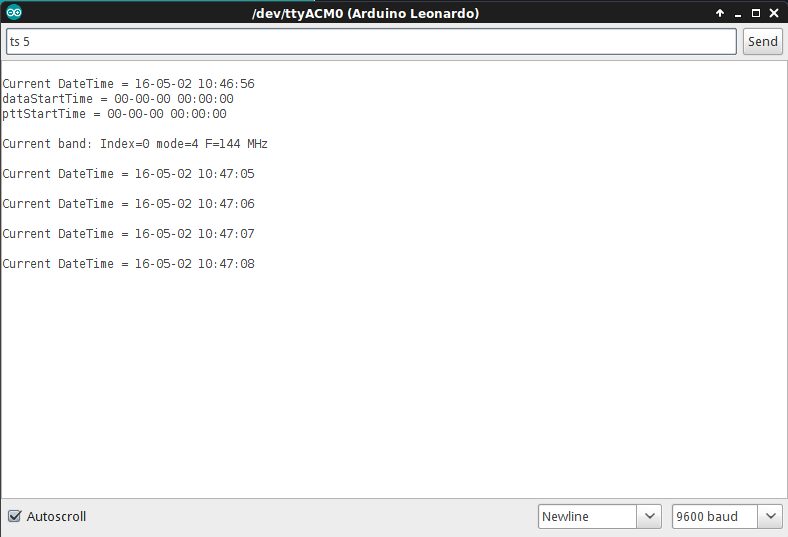
Terminal example

2 things , can the GPS be used to align the Frequency and also , can you have a display to this project
ReplyDeleteDo you mean to use 1pps from gps to organize gps-disciplined oscillator? I'll think about it, can't promise something. About display: I'm not sure which display type is most preferable.
DeleteYes, 1pps and Lat/Long for Grid and time for exact transmission. Your project can really be a very portable one.
DeleteThank you Alexander, project is working fine. Photographs of my wspr setup linked below.
ReplyDeletehttp://vu2iia.byethost7.com/wspr-ds3231.jpg
http://vu2iia.byethost7.com/24stations.png
regards
Mahesh V.
VU2IIA (INDIA)
Hello Mahesh! Great! Thank you for sharing!
DeleteHi! is there a way to use only arduino,serial gps and si5351 without the arduino shield?
ReplyDeleteIs so, please,can you tell me how to connect those parts?
The connections:
DeleteSCL - Atmega328:pin28 - si5351a:pin4
SDA - Atmega328:pin27 - si5351a:pin5
Tx from GPS to Atmega328:pin2 (rxd)
RF_OUT - si5351a:pin5 (clk0)
It is necessary to make a couple of simple changes in code for Atmega328 (Arduino Uno R3):
https://github.com/alexander-sholohov/si5351-beacon/blob/master/si5351-beacon.ino
Line 140. Should be:
#define TIME_SLICE_GPS
//#define TIME_SLICE_DS3231
Line 149: Should be
HardwareSerial& gpsSerial = Serial0;
(Change to Serial0)
Please note, you need power both atmega + si5351 from 3.3v!
This comment has been removed by the author.
DeleteThis comment has been removed by the author.
DeleteChanged to Serial because of Arduino Uno R3 (compiled ok)
DeleteI can see the output "Current band: index..." but it seems that i cannot interact at all...no command are read from the serial monitor.
Any idea?
Sorry for disturbing you again...but i really really make this thing works!
https://drive.google.com/file/d/0B_FpsyzhcEmma09NZ0J5SzhVbUU/view?usp=sharing
ReplyDeleteAn Arduino Controlled
ReplyDeleteGPS Corrected VFO.
A VFO that provides 1 to 112.5 MHz signals on two independent outputs. Use
it as a stand alone unit or with a GPS receiver to improve frequency accuracy.
UTC and six digit grid square locations are also displayed in the GPS Mode
Privet Alexander, planning a 2m jt65 beacon so your project fits perfect!
ReplyDelete2 questions:
- The configurator will not produce a meaningfull result entering a base frequency of 144479000
- what gps module are you using
73 - Norbert/OE3NFC
Hello Norbert,
DeleteI use VK18U7 GPS module, but I guess some other modules will suit as well.
Si5351 can't produce spurs-free output for JT65A 2m band. Please choose JT65B.
Hello Alexander,
ReplyDeleteVery nice and interesting project.
Assuming that I want to operate in one band only (30 meters WSPR), using just one QRP Labs bandpass filter on the QRP Labs shield without any relay board, what should I need to modify in the code to make it work simply like that. I will be using the QRP Labs QLG1 GPS rx.
Thanks in advance,
73 de Konstantinos, SV1ONW
Hello Konstantinos,
DeleteYou need only setup one line bandDescrArray (line 127 in si5351-beacon.ino).
You may leave all relay related code unchanged. It will not interfere.
Thanks Alexander, I think I got it.
ReplyDeleteI try to compile and get the following error:
si5351-beacon:149: error: 'Serial1' was not declared in this scope
HardwareSerial& gpsSerial = Serial1; // <--- Specify serial port for GPS NMEA module here
^
exit status 1
'Serial1' was not declared in this scope
I tried changing to Serial0, but again I get the same error.
Any hint?
73 de Konstantinos SV1ONW
Just one more piece of info Alexander.
ReplyDeleteIf I put:
HardwareSerial& gpsSerial = Serial
then the program compiles.
But I am not sure if this is what you mean when saying: <--- Specify serial port for GPS NMEA module here
Sorry again.
73 de Konstantinos SV1ONW
Hello Konstantinos,
DeleteFor GPS-based clock it is better to use Arduino with multiple hardware UARTs, for example MEGA 2560. However, Arduino UNO should also work. It has only one UART, so connecting GPS to the port you lost capability to interact with Arduino using terminal, but beacon itself should work.
HardwareSerial& gpsSerial = Serial1; - for Arduino with multiple UARTs
HardwareSerial& gpsSerial = Serial; - for Arduino with single UART.
Thanks a lot dear Alexander.
ReplyDelete73 de SV1ONW
Thank you Alexander for this nice project. I selected it out of many other projects to make own experiments with WSPR on Arduino.
ReplyDeleteAfter trying your project code, I decided to modify this code for some enhancements:
- use of the NT7S-library for the si5351 (enables the frequency as parameter with 10 mHz resolution instead of your preconfigured parameters)
- add a small ublox6-GPS-system with a special digital control algorithmn to correct the thermal and absolute deviation of the xtal in the si5351 breakout board: result: a universal GPS controlled generator with an absolute frequency precision of roughly about 10^-8 (=10 ppb) (You find them on the well known Chinese delivery pages for about 3 US$.)
- adding a second generator for wspr -- result now in parallel two different wspr-generators at the same time
- some misc additions to the code, special for WSPR.
All is running on a Arduino Nano 328P with nearly 28 kBytes of program code.
About my experiments and the WSPR-results, my special hardware, I hold a talk on the ham radio convention in June 2018 in Friedrichshafen, Germany. (in german, foils available on request)
I like to offer the additions to the repository at github or for a code review, if this is interesting for you on request.
vy 73
Michael, DK5HH
Hello Michael, I’m glad you like the project!
DeleteAbout si5351 and preconfiguerd parameters: In the project I configure si5351 to utilize integer divider only. This allows to keep spoor level as low as possible. It is important on high bands (6m,4m,2m). The lib you mentioned utilizes fractional divider that allows to use such a small step.
Yes, please fork the project on github and make necessary changes. However I will not promise I will include all changes into the project. I would like to keep the project simpler.
Thank you.
73, Alexander RA9YER
This comment has been removed by the author.
ReplyDeleteHi Alex,
ReplyDeleteI have connect DS3231 like on your picture but setdate command do not update clock. I have change connect DS3231 instead pins 2 and 3 to PIN's Arduino UNO: SDA ,SCL and now setdate command work. In your code in ds3231.cpp you defined #define USE_ARDUINO_I2C and I can not find where is mapped to PINS 2 and 3 on Arduino UNO. If we put DS3231 to PINS 2 and 3 communications with DS3231 don't work. What about 1pps wire to PIN number 4 , where is defined in your code ?
Hello,
DeleteOn my Arduino Leonardo SDA/SCL are mapped to 2/3. On Arduino Uno they are mapped to A4/A5.
1pps pin is mapped to Arduino Pin 4 - please see si5351-beacon.ino line 78 .
Useful Pinout-Diagram https://www.circuito.io/blog/arduino-uno-pinout/
Hi Alex,
ReplyDeleteBecause I have use SI5351 https://learn.adafruit.com/adafruit-si5351-clock-generator-breakout/overview with 25 MHz Xtal I found in your source definition of XTAL in si5351-beacon/src/utils/jt_band_params.cpp #define XTAL_FREQUENCY_IN_KHZ (27000)
after correct this value to 25000. But found other file si5351-beacon/src/si5351/radio/register_map.h and I am not sure that I need have other values for 25 Mhz Xtal SI5351 ???
Hi Alexander, I really like your project and have found it as a good jumping off point to mod it to what I need. I was wondering if you could take a few cycles to explain how your 1PPS code is working (lines 308-311). I'm probably being thick but I'm not following the logic. Could you explain more specifically please? I'm asking because I am trying to use the Adafruit Ultimate GPS library for the Arduino and want to do something similar. But before that happens I figured I should follow your logic first.
ReplyDeleteHello! I’m glad you like the project! About 1pps: Imagine you have ds3231 only. It has 1pps output pin. It has logic “0” at first half a second, and logic “1” at another half a second. The function loop() is called hundred of times per second, so we appear at lines #308-#311 very often in a loop. Look at line #310, there we detect falling edge of the 1pps signal. The variable nextSecondDetected becomes TRUE only once at each second. Later at line #330 we make some actions only when the new second is detected. Retrieving data from chip takes some time, so it good reason to make some actions only when it is necessary. Well, back to GPS. When I implemented GPS, I decided not to make big changes in the code. The function TimeSliceGPS::get1PPS() (file time_slice_gps.cpp:36) just emulates 1pps behavior.
DeleteHope this helps.
Добрый день, Александр! Использую Вашу разработку уже достаточно долго. Спасибо!
ReplyDeleteА существует ли вариант кода с поочередной передачей WSPR и CW? Т.е. на 0 минуте отправляем WSPR, на второй телеграфом (другая частота), на 4 минуте снова WSPR и т.д..
hello Alex I am ik1hgi is not that you can realize the system also FSF4W a system that is taking to use on the bands I prefer 472khz wspr thank you 73 ik1hgi Tony
ReplyDeletehi Alex I am ik1hgi is not that you can make the system also FSF4W a system with Arduino beacon!!! some transmit it with the program WSJT-Xto use on the bands I prefer 472khz wspr thanks 73 ik1hgi Tony
ReplyDeleteHello Tony, technically si5351 can produce fst4w signal that a receiver can decode. However, fst4 specification says it must be 4-GFSK modulation. It is virtually “ideal” signal with narrowest bandwidth possible. Well, I think a simple solution on si5351 can produce only dirty fst4w signal.
Delete